
I. TBASIC Components: Statements, Functions and Operators
1. Integer Variables
The TBASIC compiler in TRiLOGI Version 6.0/7.0 supports full 32-bit integer computations. All integer constants are treated as 32-bits and there are 26 variables (A to Z ) that are 32 bits in length. These variables can represent numbers between -231 to +231. The remaining system variables and data memory DM[n] are all 16-bit variables which means that they can only store numbers between -32768 to +32767. These 16-bit variables are:
DM[1]..DM[4000] (Total = 4000), input[n], output[n], relay[n], timerbit[n], ctrbit[n], timerPV[n],ctrPV[n], HSCPV[n], (High Speed Counter). TIME[n], DATE[n].
However, all numeric computations in TBASIC are carried out in 32-bit signed integers, regardless of the bit-length of the variables involved in the numerical expression. All variables used in TBASIC are "GLOBAL variables - this means that all these variables are shared and accessible by any of the 128 custom functions.
2. Integer Operators
a) Arithmetic Operators: +, -, *, /, MOD
b) Bit-wise Logical Operators:
Symbol Operation Example & logical AND IF input[1] & &H02 ... | logical OR output[1] = A | &H08 ^ Exclusive OR A = RELAY[2] ^ B ~ logical NOT A = ~timerPV[1]
c) Relational Operators : Used exclusively for decision making expression in statement such as IF expression THEN ..... and WHILE expression ....
Symbol Operation Example = Equal To IF A = 100 <> Not Equal To WHILE CTR_PV[0]<> 0 > Greater Than IF B > C/(D+10) < Less Than IF TIME[3] < 59 >= Greater Than or Equal To WHILE X >= 10 <= Less Than or Equal To IF DM[I] <= 5678 AND Relational AND IF A>B AND C<=D OR Relational OR IF A<>0 OR B=1000
3. String Data
A string is a sequence of alphanumeric characters (8-bit ASCII codes) which collectively form an entity. A string constant may contain from 0 to 70 characters enclosed in double quotation marks. e.g.
"TBASIC made PLC numeric processing a piece of cake!"
"$102,345.00"
TBASIC supports a maximum of 26 string variables A$, B$ ... Z$. Each string variable may contain from 0 (null string) up to a maximum of 70 characters.
4. String Operators
a) Assignment Operator: A string variable (A to Z, DM and system variables, etc) may be assigned a string expression using the assignment statement:
A$ = "Hello, Welcome To TBASIC"
Z$ = MID$(A$,3,5)
b) Concatenation Operators: Two or more strings can be concatenated (joined together) simply by using the "+" operator. e.g.
M$ = "Hello " + A$ + ", welcome to " + B$
If A$ contains "James", and B$ contains "TBASIC", M$ will contain the string: "Hello James, welcome to TBASIC.
c) Comparison Operators: Two strings may be compared for equality by using the function STRCMP(A$,B$). However, the integer comparator such as "=", "<>", etc cannot be used for string comparison.
5. TBASIC Statements and Functions
Most of the statements and functions of the powerful TBASIC language is tabulated below together with brief explanations for their purposes.
| Command | Purpose |
| ABS(x) | To return the absolute value of x |
| ADC(n) | To return the value from the A/D Converter #n. |
| ASC(x$,n) | To return the ASCII code for the nth char. of x$. |
| CALL n | To call another Custom Function CusFn #n. |
| CHR$(n) | To convert a number n into its corresponding ASCII character. n must be between 0 and 255) |
| CLRBIT v,n | To clear the Bit #n of the integer variable v to '0'. |
| FOR ... NEXT | To execute a series of instructions for a specified number of times in a loop. |
| GetCtrSV (n)
GetTimerSV (n) |
Return the Set Value (S.V) of Counter or Timer #n. |
| GETHIGH16(v) | returns the upper 16-bit of a 32-bit integer variable |
| GOTO @ n | To branch unconditionally to a specified line with label @n within the present Custom Function. |
| HEX$(n) | To return a hexadecimal string expression of n. |
| HEXVAL(x$) | To convert hexadecimal number in string x$. |
| HSTIMER n | To define PLC Timer #1 to #n as “High Speed Timers” (HST) with time-base of 0.01s. |
| HSCDEF ch, fn,v | Enable and set up parameters for the High Speed Counters channel ch. |
| HSCOFF ch | Disable High Speed Counter #ch |
| IF .. THEN .. ELSE .. ENDIF | To make a decision regarding program flow based on the result returned by an expression |
| INPUT$(ch) | To get a string from communication port ch. |
| INTRDEF ch, fn,e | Enable Interrupt Input channel ch and the interrupt service routine CusFn # fn |
| INTROFF ch | Disable Interrupt Input channel ch. |
| LEN(x$) | To return the number of characters in x$. |
| LOAD_EEP(addr) | To obtain16-bit integer value from the EEPROM. |
| LSHIFT i,n | To shift 1 bit to the left the 16-bit integer variable I, |
| MID$(x$,n,m) | To extract a string of m characters from x$, beginning from the nth character |
| PAUSE | To set a breakpoint for executing the CusFn |
| PIDdef ch, lmt, P,I,D | To set up the parameters for a Proportional, Integral and Derivative (PID) Controller function. |
| PIDcompute
(ch,E) |
Computes the output for the error E using the P,I,D value set by the PIDdef command. |
| PRINT# n x$;.. y; z.... | To send the string formed by parameter list (x$; y; z) to communication port # n. |
| PMON ch
PMOFF ch |
PMON enables Pulse Measurement Function at channel #ch. PMOFF disables the channel |
| PULSEFREQUENCY
PULSEPERIOD PULSEWIDTH |
Return in Hz the frequency of the last input pulse ; Return in milli-seconds the width and period of the input pulses arriving at channel ch. |
| REFRESH | To immediately refresh of the physical outputs. |
| RESET | To perform a software reset of the PLC |
| RETURN | Unconditionally return to the caller function. |
| REM (or ') | Put explanatory remarks in the program. |
| RSHIFT i,n | To shift the integer variable i 1 bit to the right. |
| SAVE_EEP data, addr | To store a 16-bit integer data in the user's definable EEPROM address addr. |
| SETBAUD ch, baud | To set the communication “Baud Rate” of the PLC's serial channel #ch |
| SETBIT v,n | To set the bit #n of the integer variable v to '1'. |
| SetCtrSV n, val
SetTimerSV n, val |
Change the Set Value (S.V,) of the Counter #n or Timer #n to value |
| SETDAC n, x | To set D/A converter #n to x |
| SETTHIGH16 v,d | To assign the upper 16-bit of a 32-bit variable v |
| SETPWM n, x, y | To set PWM channel #n with duty cycle x%. |
| STEPCOUNT(ch) | Track the number of steps sent since STEPMOVE. |
| STEPSPEED ch, pps, acc | Set the speed pps and acc for the PLC's stepper motor controller (pulse-generator) channel #ch. |
| STEPMOVE ch, count, r | Activate the stepper motor pulse generator channel #ch to output count number of pulses. |
| STEPSTOP | Immediately terminate Stepper controller #n |
| STR$(n) | Convert the number n into a string expression. |
| STRCMP(A$, B$) | Comparison of two strings: A$ and B$. |
| STRUPR$(A$) | To return all upper-case copy of A$. |
| STRLWR$(A$) | To return all-lower-case copy of A$. |
| TESTBIT (v,n) | To return the logic state of bit #n of the variable v. |
| WHILE expression .... ENDWHILE | To execute a series of statements in a loop as long as a given condition is true. |
| VAL(x$) | To return a value of a number in the string x$. |
II. TBASIC Support for Special Inputs and Outputs
Besides typical ON/OFF type I/Os and Analog I/Os, some of the T100MX first 8 ON/OFF inputs can be configured as special inputs such as High Speed Counter, Interrupt and Pulse Measurement. Some of the first 8 outputs can also be configured as PWM and the stepper pulse-outputs, as follow:
| Input # | High Speed Counter | Interrupt | Pulse Measurement | Output # | Stepper pulse | Pulse Width Modulation | |
| 1 | - | - | - | 1 | - | - | |
| 2 | - | - | - | 2 | - | - | |
| 3 | Ch #1: Phase A | Ch #1 | Ch #1 | 3 | - | ||
| 4 | Ch #1: Phase B | Ch #2 | Ch #2 | 4 | - | ||
| 5 | Ch #2: Phase A | Ch #3 | - | 5 | Ch #1 | - | |
| 6 | Ch #2: Phase B | Ch #4 | - | 6 | Ch #2 | - | |
| 7 | - | - | - | 7 | - | Ch #1 | |
| 8 | - | - | - | 8 | - | Ch #2 |
1. Interfacing Stepper Motors
| No. of Channels | 2 |
| Maximum Pulse Rate (pps) | 30000 (single channel running)
15000 (two channels running) |
| Maximum Load Current | 1A @24V DC |
| Maximum number of steps | |
| Relevant TBASIC commands | STEPSPEED, STEPMOVE, STEPSTOP, STEPCOUNT( ) |
The T100MX built-in Stepper-Motor Controller generates the required number of "pulses" according to the defined acceleration and maximum pulsing rate specified by "STEPSPEED" and “STEPMOVE” commands. The SETPSTOP command can immediately interrupt and stop the stepper motor. STEPCOUNT( ) function tracks the number of steps sent to the stepper motor since the beginning of STEPMOVE command.
2. PWM Outputs
| No. of Channels | 2 |
| Duty Cycle range | 0.00 to 100.00 |
| Actual Resolution | 0.4% |
| Available Frequencies (Hz) | 16, 32, 63, 250, 500, 2000, 8000 and 32000 Hz |
| Relevant TBASIC commands | setPWM |
Pulse-Width Modulation (PWM) is a highly efficient and convenient way of controlling output voltage to devices with large time constant, such as controlling the speed of a DC motor, the power to a heating element or the position of a proportional valve. PWM works by first turning the output to full voltage for a short while and then shutting it off for another short while and then turn it on again and so on in accurate time intervals. This can be illustrated in the following diagram:
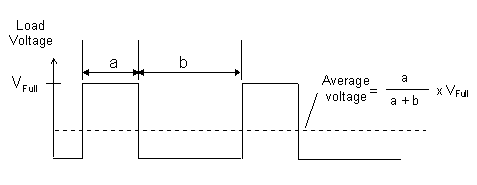 |
The average voltage seen by the load is determined by the “duty cycle” of the PWM wave form. The duty cycle is defined as follow:
Duty Cycle = a / (a+b) x 100% Period = (a + b) Frequency = 1/period Hz |
The TBASIC SETPWM statement controls the frequency and duty-cycle settings of the PWM channel. The T100MX PLC features two channels of PWM on its outputs #7 and #8. Since these two outputs are high voltage, high current outputs (24V, 1A) they can be used to directly control the speed of a small DC motor of up to maximum of 1A current. They can also directly drive proportional (variable position) valves whose opening is dependent on the applied voltage.
The advantage of using PWM is that you can easily amplify the drive current to a larger load such as larger permanent magnet DC motor by using low cost DC Solid-State Relays (SSR) to boost the current switching capability. In such case the T100MX PWM output is only used to drive the emitter portion of the SSR. The load is driven by the receiver portion of the SSR. Using SSR has the added advantage of isolating the CPU from the high current load.
3. High Speed Counter Inputs - Interfacing to Rotary Encoder
| No. of Channels | 2 |
| Counter Range | |
| Maximum acceptable pulse rate | 4000 Hz |
| Quadrature signal decoding | Automatic |
| Relevant TBASIC Commands | HSCDEF, HSCOFF, HSCPV[ ] |
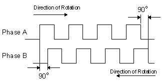
Input #3, 4 and Inputs #5, 6 form two channels of high speed counter inputs which can interface directly to a rotary encoder that produces “quadrature” outputs. A quadrature encoder produces two pulse trains at 90o phase shift from each as follow:
 |
Explanation:
When the encoder shaft rotates in one direction, phase A leads phase B by 90 degrees. When the shaft rotates in the opposite direction, phase B will lead phase A by 90 degrees. The quadrature signals therefore provide an indication of the direction of rotation. |
T100MX handles the quadrature signals as follow: if the pulse train arriving at input #3 leads the pulse train at input #4, the High Speed Counter (HSC) #1 increments on every pulse. If the pulse train arriving at input #3 lags the pulse trains at input #4, then the HSC #1 decrements. Note that if input #4 is OFF, then pulse trains arriving at input #3 is considered to lead the input #4 and HSC #1 will be incremented. Likewise if input #3 is OFF, then pulse trains arriving at input #4 will decrement HSC #1. Input #5 and #6 form the inputs for High Speed Counter channel #2 and they operate in the same way as Input#3 and #4 for HSC#1 described above.
The fact that T100MX PLC automatically takes care of the direction of rotation of the quadrature encoder greatly simplifies the programmer's task of handling high speed encoder feedback. The HSCDEF statement can be used to define a Cusfn to be executed when the HSC reaches a certain pre-defined value. Within this Cusfn you can define the action to be taken and define the next Cusfn to be executed when the HSC reaches another value.
4. Interrupt Inputs
An interrupt input may occur randomly and the CPU will have to immediately put down whatever it is doing and start “servicing” the interrupt. Hence the CPU responds much faster to an interrupt input. In addition, interrupts are “edge-triggered”, meaning that the interrupt condition occurs when the input either changes from ON to OFF or from OFF to ON. Consequently, the input logic state need not persist for longer than the logic scan time for it to be recognized by the CPU.
Any one or all of inputs #3 to #7 can be used as interrupt inputs when defined by the INTDEF statement. The Interrupt inputs may also be defined as either rising-edge triggered (input goes from OFF to ON) or falling-edge triggered (input goes from ON to OFF). When the defined edges occur, the defined Custom Function (CusFn) will be immediately executed irrespective of the current state of execution of the ladder program.
5. Using Pulse Measurement Inputs
T100MX provides a very straight forward means to measure the pulse width or frequency of a square-wave pulse-train arriving at its Pulse Measurement (PM) inputs #3 or #4. To use the input to measure pulse width or frequency, execute the PMON statement to configure the relevant input to become a pulse measurement input. Thereafter the pulse width (in ms) or the pulse frequency (in Hz) can be easily obtained from the PULSEWIDTH(n) or PULSEFREQUENCY(n) function.
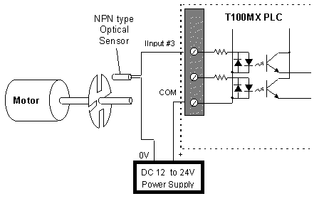
Setting Up a Simple Tachometer or Encoder
- One useful application of the PM capability is to measure the speed of rotation of a motor. A simple optical sensor, coupled with a rotating disk with slots fitted to the shaft of a motor can be fabricated economically. When the motor turns, the sensor will generate a series of pulses. The frequency of this pulse train relates directly to the rotational speed of the motor and can be used to provide precise speed control.
This setup can also double as a low cost position-feedback encoder, since the number of pulses counted can be used to determine the displacement.
- 2) Some transducers incorporate Voltage-Controlled-Oscillator (VCO) type of outputs which represent the measured quantities in terms of varying frequency of the output waveform. Such transducers may be used conveniently by T100MX using the pulse measurement capability. However, the frequency of such signal must be below 4000Hz and the output should be conditioned to square wave using Schmitt-Trigger type IC driver.
III. Application Examples for T100MD PLC and Sample Programs
Programming the M-series built-in hardware is unbelievably easy using TRiLOGI. We present 5 examples here to illustrate our point. These are fully functional projects and they represent challenging tasks that demand powerful PLCs, yet programming them using TRiLOGI is totally effortless. Compare the following examples with the amount of programming effort needed on other makes of PLCs to handle the same tasks. You will quickly realize the big saving of programming time when using TRiLOGI together with the M-series PLCs!
1. (a) Display Alphanumeric Messages on built-in LCD Display (For T100MD-1616 only)
| Only T100MD-1616 has built-in interface for industry standard alphanumeric LCD module which can range from 1x8, 2x16, 2x20 or 4x20 types.
Assignment: Every 1 second, display a message as follow: Full scale A/D is 4096. |
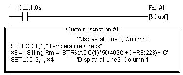 Comments: Every one second, the special bit Clk:1.0s closes and activates Function #1. Within the Custom Function #1, ADC(1) reads the A/D converter #1 and converts into degrees. SETLCD displays the string. |
1 (b) Display Alphanumeric Messages on External Serial LCD Display: MDS100
| MDS100 is an optional 4 lines x 20 characters LCD display connected to the PLC's RS485 port (serial port #3). Both T100MD-1616 and T100MX can use MDS100, although the only reason for T100MD user to use MDS100 will be to have more than 1 LCD display.
Every 1 second, display a message as follow: Full scale A/D is 4096. |
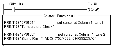
Comments: Every one second, the special bit Clk:1.0s closes and activates Function #1. Within the Custom Function #1, ADC(1) reads the A/D converter #1 and converts into degrees. PRINT #3 displays the string. |
2. Motion Control of Stepper Motor
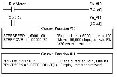
| T100MX generates pulses to feed to stepper motor driver. The maximum speed, acceleration/deceleration and total number of pulses to generate are definable using TBASIC.
Assignment:
|
 |
3. Activate Events at Scheduled Times
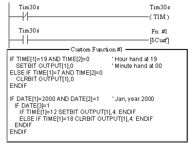
| T100MX has Real Time Clock which keeps track of Date and Time and can be used to activate events at scheduled time.
Assignment:
Note : 1. Tim30s activates Function #1 every 30 seconds. 2. Output #1 is bit #0 of the variable output[1]. The statement SETBIT output[1],0 turns ON output #1. 3. Actually it may not be necessary to check the minute hand since when the RTC turns from 18:59 to 19:00, the output will be turned ON as long as TIME[1]=19. Only when TIME[1]=7, then output #1 needs to be changed. |
 |
4. Automatic Climate Control System
Assignment:
|
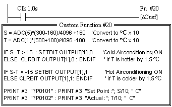
Comments: One decimal place is used for temperature reading. All temperature readings are x 10 times. Hence 16.0 degree C is |
5. Closed-Loop PID Control of Heating Process
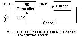
PID Controller Transfer Function: Assignment:
Full scale A/D range is 4096. Range of Set Point: A/D #5 = 0 => 50 C Range of Sensor: ADC#1 =0 => 0 C |
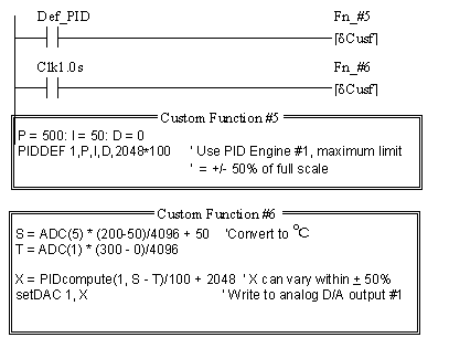
Note:
|

